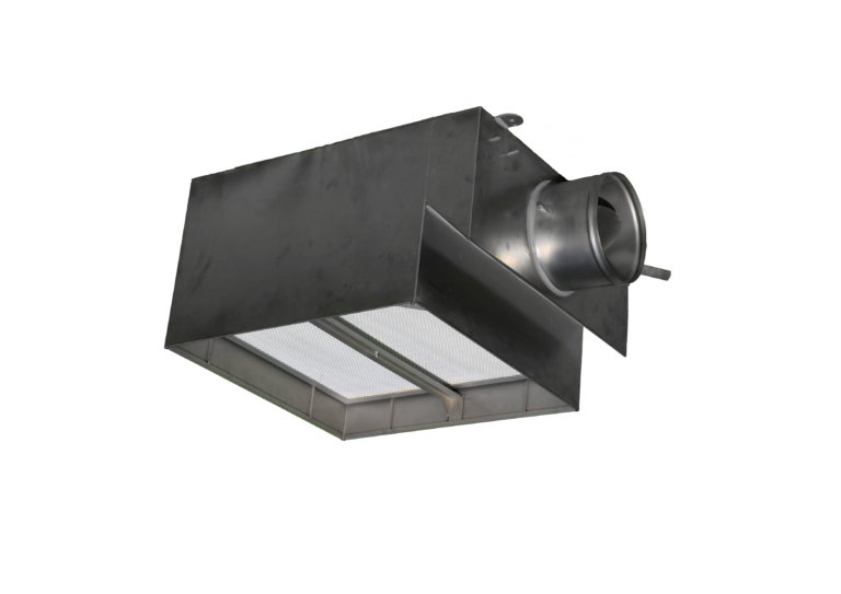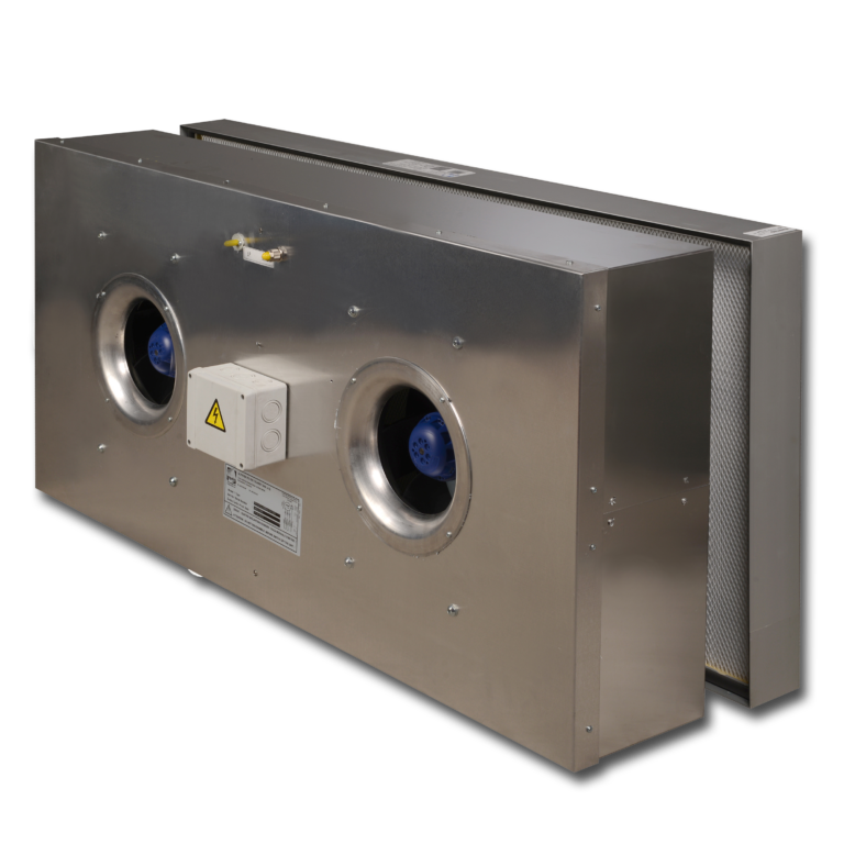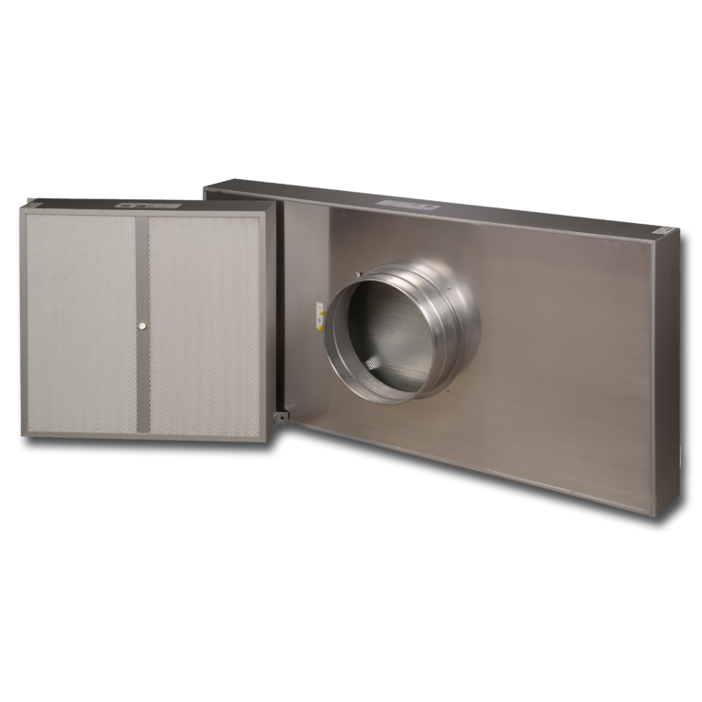
A fan filter unit supplies local fan pressure to move air through its filter; a conventional HEPA terminal box relies on a fan elsewhere in the air system. Choose between them by checking airflow, available pressure, the return-air route, controls and maintenance access. Either can serve a cleanroom when the complete system meets its requirements. Berkeley Lab: fan-filter units, Ulpatek HEPA Filter Box
Adding a motor above the filter does not give the room a particular cleanliness class.
What changes when the fan moves to the ceiling?
A HEPA terminal box receives air from the supply system, passes it through its filter and distributes it into the room. In a ducted arrangement, the central fan must provide enough pressure for the complete path, including the terminal filter.
An FFU integrates a fan, controller and filter in one module. Berkeley Lab describes FFUs as modular recirculation equipment and identifies the air path, controls and system pressure as design factors. The module choice still needs to fit the complete recirculation layout. Berkeley Lab: fan-filter units
An FFU recirculating room air still needs a properly designed return path. It also does not, by itself, provide the building's required outdoor air, humidity control, cooling capacity or exhaust replacement. Include those duties in the design before choosing the ceiling modules.

Start with the room requirements
Define the required cleanliness, operating state, process protection, airflow pattern and room pressure relationships. Then select the filtration and air-distribution arrangement that can deliver them.
ISO 14644-1:2015 classifies air cleanliness by airborne particle concentration. It does not classify a room by the name of its terminal device. ISO 14644-4:2022 addresses the process of translating requirements into cleanroom design, construction and start-up without prescribing one technology for every project. ISO 14644-1:2015, ISO 14644-4:2022
For a unidirectional clean zone, total volume flow alone is not enough: discharge area, distribution, obstructions and the path across the process matter. For a room with mixed airflow, supply and return locations still affect how contaminants are removed. Neither issue disappears when an FFU is selected. Berkeley Lab's cleanroom guidance identifies airflow quantity, uniformity and speed as design considerations for contamination control. LBNL-58639: energy-efficient cleanrooms and FFUs
Use this decision table before comparing prices
The table is a selection aid. The final choice depends on the complete system calculation and the equipment actually offered.
| Project condition | HEPA terminal box is worth considering when… | FFU is worth considering when… |
|---|---|---|
| Existing air supply | The AHU and distribution system can provide the required flow and pressure throughout filter service | Local fan assistance can be integrated within the selected FFU's inlet-pressure and control limits |
| Large recirculation duty | A central recirculation system and suitable distribution space are available | A usable common plenum and return path support distributed recirculation |
| Changing production layout | Terminal positions and duct branches are relatively fixed | Modules may need repositioning or staged expansion |
| Maintenance strategy | The facility prefers fewer distributed motors and controllers | The facility can support module-level electrical and mechanical maintenance |
| Control requirements | Central and branch controls can maintain each terminal's duty | Local airflow adjustment and unit-level monitoring are useful |
| Ceiling constraints | The box, inlet connection, diffuser and service clearances fit | The fan module, inlet space, supports, cables and service clearances fit |
Scroll the table sideways to see all columns →
Do not decide from purchase price alone. Include the central fan duty, return-air construction, electrical distribution, controls, access provisions and commissioning work. A low terminal price may be offset by other system costs.
Pressure budget: check the loaded filter, not just the clean one
For a terminal box, calculate the pressure available at its inlet relative to the room, at the required airflow. Then account for losses through the selected terminal assembly. Upstream duct losses belong in the central system calculation; do not subtract them twice.
Consider this illustrative terminal calculation. The values are design assumptions, not Ulpatek product data:
| Item at the required terminal airflow | Clean-filter condition | Selected end-of-service condition |
|---|---|---|
| Filter pressure drop | 150 Pa | 300 Pa |
| Box and diffuser losses | 35 Pa | 35 Pa |
| Balancing allowance | 30 Pa | 30 Pa |
| Required inlet-to-room pressure | 215 Pa | 365 Pa |
| Available inlet-to-room pressure | 300 Pa | 300 Pa |
| Remaining margin | +85 Pa | −65 Pa |
Scroll the table sideways to see all columns →
The clean-filter condition works. The selected loaded-filter condition does not: the system cannot deliver the same flow with a 65 Pa shortfall under these assumptions. The 300 Pa filter figure here is a design assumption, not a universal replacement threshold.
Possible responses include increasing available fan pressure, reducing system losses or selecting a suitable lower-resistance filter and terminal arrangement. Adding an FFU is another engineering option only if its permitted inlet conditions, fan curve and controls suit the system.
“EC motor” is not a complete control specification
The motor type does not tell you how the system regulates airflow. Ask whether the unit runs at a fixed setting, maintains a torque characteristic or uses a constant-flow program. Ask what it measures, what it alarms and what happens when it reaches its available speed or power limit.
Specify the start-up sequence, normal control, alarm thresholds and failure response. For a common-plenum system, check how changes in module demand affect plenum pressure and make-up air control. For either arrangement, verify room pressure relationships separately; a terminal airflow setpoint is not a room-pressure measurement.
Count units at the actual duty
Suppose the project has already established that it needs 8,100 m³/h of filtered supply or recirculation. If a candidate unit delivers 900 m³/h at the required pressure and acceptable sound level, the arithmetic minimum is nine units. At 600 m³/h per unit, it is fourteen after rounding up. Those fourteen units would be balanced to the required total—about 579 m³/h each if the flow is shared equally—with their performance checked at that setting.
Those numbers are a sizing illustration, not an airflow recommendation for any ISO class. The layout may need more terminals for airflow distribution, coverage or backup capacity. The catalogue's maximum airflow may also be unsuitable for the selected filter, sound limit or fan operating point.
Ask the supplier to state the delivered flow, filter resistance, inlet conditions, electrical input and sound data at the same selection point. A free-air fan value is not an installed filtered-air capacity.
Compare energy at the system boundary
An FFU is not automatically more efficient than a centrally supplied terminal box. Berkeley Lab's research found that system performance depends on the equipment and airflow paths; it also cautioned that FFU systems can be less efficient than other arrangements. Its older measurements are not current product rankings, but the need to compare complete operating conditions remains relevant. LBNL-58639
Compare fan electricity for the whole arrangement, including any upstream fan still needed with the FFUs. Use the same required airflow, operating hours and filter-loading assumptions. Consider the associated cooling duty as part of the wider HVAC assessment.
A small power difference per module adds up across a ceiling. If forty units each use 15 W less at the same duty for 8,760 hours, the calculated saving is 5,256 kWh/year. That is an illustration, not an Ulpatek savings claim. It shows why operating-point power matters more than an unqualified “low wattage” claim.
ISO 14644-16:2019 provides guidance on energy efficiency while maintaining cleanroom performance. Reducing the flow below what the process needs is not an energy comparison between equivalent designs. ISO 14644-16:2019
Design the maintenance access now
Decide how the filter, motor, controller and prefilter will be accessed. Room-side filter replacement does not necessarily mean room-side access to every other component. Check the drawing and replacement procedure rather than interpreting one access label as a promise for the entire unit.
Also specify seal geometry, accessible test connections, diffuser removal and the practical space needed for verification. Ulpatek's HEPA Filter Box range provides different sealing surfaces and connection arrangements; these are selection details that should be resolved before the ceiling is built. Ulpatek HEPA Filter Box
Installed-system verification remains necessary whichever arrangement is chosen. Agree the applicable tests, operating states and acceptance requirements in the qualification plan. ISO 14644-3:2019 provides cleanroom test methods, including methods for different airflow arrangements and occupancy states. ISO 14644-3:2019
What Ulpatek needs to make a useful selection
Ulpatek manufactures both terminal boxes and FFUs. Its published FFU range includes AC and EC fan options, with different filter-replacement arrangements. Specify the required options; do not assume every configuration includes the same controls or accessories. Ulpatek technical catalogue, FFU section