Test Methods
There are two main sources of filter testing which are US standards (ASHRAE, IEST, MIL) and European standards (CEN, EN779 and EN1822). ASHRAE uses “ Average Arrestance” efficiency for gross filters and “Atmospheric Dust Spot Efficiency” for fine filters. On the other hand, in EN779: 2000 both coarse and fine filters utilize the method of measuring the efficiency through optical particle counters on both sides of the filter by feeding it with air that contains DEHS (or equivalent). In Europe, CEN standards are being used for HEPA and ULPA filter tests, while in USA, IEST and MIL recommended publications are being used. HEPA filters efficiency has been defined according to the 0.3 µm at IEST standards. However at EN 1822 HEPA efficiency has been defined at MPPS (Most Penetrating Particle Size). The filter test patterns in these two standards are also changing. For filter tests, IEST recommends particle counters and photometers, while EN 1822 requires particle counters. According to the user requirement ULPATEK filters can be tested in accordance with both European (CEN) and US standards, moreover individual test certificates are given for HEPA and ULPA filters.
Oil Thread Leak Test EN 1822-4
The leak test serves to verify that filter elements have no leaks which mean local penetration values below the permissible limits (see EN 1822-1, table 1). The Oil Thread Leak Test may be carried out as an alternative leak test method for filters of group H (classes H13 and H14). The reference for this leak test is however the particle count scan method as described in the body of this standard. The Oil Thread Leak Test is also acceptable as a test procedure for filter shapes for which the scan method cannot be applied (e.g. filter elements with Vbank media panels or for cylindrical filters).
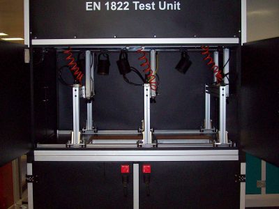
The leak test serves to verify that filter elements have no leaks which mean local penetration values below the permissible limits (see EN 1822-1, table 1). The Oil Thread Leak Test may be carried out as an alternative leak test method for filters of group H (classes H13 and H14). The reference for this leak test is however the particle count scan method as described in the body of this standard. The Oil Thread Leak Test is also acceptable as a test procedure for filter shapes for which the scan method cannot be applied (e.g. filter elements with Vbank media panels or for cylindrical filters). The Oil Thread Leak Test is a qualitative test method where the absence of leaks is demonstrated visually. Therefore, it is essential to carry out regular training of the test personnel and to verify the sensitivity of the procedure and the method at regular intervals by using reference filter elements with well-defined leaks, characterized by the reference scan test method. The local penetration of the leaks in the reference filter elements shall be between the limit values for the filter class defined in EN 1822-1, table 1 and maximum double the corresponding limit value. In the test set-up the filter shall be subjected to a flow of a polydisperse oil-drop aerosol with a speed of approximately 1,3 cm/s (42 m³/m²/h), which may be varied to optimize the procedure. The filter shall be placed horizontally on a diffuser or box. The test filter mounting assembly shall ensure that the test filter can be sealed and subjected to the flow in accordance with the requirements. It shall not obstruct any part of the filter cross sectional area. The polydisperse test aerosol shall be generated by nebulising from a liquid aerosol substance in accordance with para. 4.1 of EN 1822-2. The median value of the particle diameter shall lie between 0.3 and 1.0 µm. The mass concentration shall be 1.5 g/m³ (determined by gravimetric methods). The downstream side of the filter shall be illuminated from vertically above with a white (4000K) fluorescent lamp or halogen lamps. The brightness of the lamp shall be > 1000 Lux at the working plane. The surroundings of the filter shall be darkened, and the observational background shall be black. Uncontrolled air currents from the surroundings shall be screened out. Under these conditions, leaks can be recognized in from of a clearly visible oil thread which appears due to the leakage. If no oil threads can be seen the filter up to class H14 is free from leaks as per the leak limit values defined in EN 1822-1, table 1. The position and the brightness of the lamp may be adapted to the examiner’s subjection perception by using reference filter elements with well-defined leaks characterized by the scan test method. It is also recommended that reference filters shall be used that are well-defined leaks in the medium and in the frame corners close to the sealant.
EMERY (DOP) Test (ISPE)
HEPA filters are normally used only where an extremely high level of cleanliness or purity is required. The requirement may be due to problems caused by the presence of particulates or physiological problems caused by viable airborne organisms. In any event, the efficiency of every filter is of paramount importance and must be measured in an appropriate way. Mil-Std-282 is recognized as the standard for “hot” DOP efficiency testing and is used for compliance with many HEPA filter specifications. It is also recognized as being “monodisperse 0.3 micron particles” as referenced in EPA and OSHA definitions for HEPA filters.
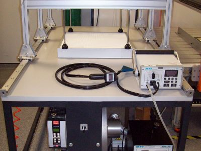
DOP (dioctylpthalate) is an oil commonly used with vinyl resins to make soft vinyl plastics. It is also used by air filter manufacturers and various testing agencies to make an aerosol to test the effectiveness of air filters. Other oil-like materials, like DOS, can be substituted with similar results. The DOP aerosol used to challenge HEPA filters to test for efficiency by this standard is known as “hot” or “thermally generated” DOP because it is derived from heated dioctylpthalate oil. Sophisticated equipment is used for carefully controlling oil and air temperatures, air flow rates and mixing conditions. This “hot” DOP aerosol has a very narrow particle size distribution (monodisperse). Because the only way to determine the efficiency of a filter on a specific particle size (fractional efficiency) is to test with particles of that size, DOP is used to produce a high concentration of 0,3 micron particles – that which theory indicates and has historically been considered to be the most penetrating of filter media. For each test, the average aerosol concentration is measured both upstream and downstream of the filter with a photometer. The inefficiency or penetration in percent can therefore be determined and recorded on the filter label. For example, a filter with a penetration of .008% would mean it was 99.992% efficient, well above the minimum of 99.97% for HEPA efficiency. DOP aerosol can be generated in the field but the equipment used, while relatively simple and portable, cannot produce truly “hot” DOP that is monodisperse. The DOP generated by such equipment is “cold” DOP which having a broad particle size distribution is polydisperse. Such an aerosol is useful for field testing for leaks and ensuring the integrity of an installation, however, without the ability to particle count the 0,3 micron size particles, “cold” DOP does not provide the ultimate test of filter efficiency. The penetration or efficiency of a filter is strongly affected by the particle size of the challenge aerosol. A small change in particle size can have a significant effect on penetration. The smaller the particle, the lower the efficiency until the maximum penetrating particle size is reached. As indicated earlier, “cold” DOP has a broad particle size with larger average size than “hot” DOP. Efficiencies are, therefore, higher with “cold” DOP than with “hot” DOP. The control of temperatures and flow rates with the equipment is critical to maintaining a consistently tight particle distribution which allows for consistent and reproducible efficiency measurements. Where “cold” DOP can be useful in determining HEPA filter efficiency is when testing in accordance with IEST-RP-CC007.1. For each test, particle counters are calibrated to simultaneously count the number of 0,3 micron particles both upstream and downstream of the filter. Providing the “cold” DOP challange aerosol contains a statistically significant number of 0,3 particles, the inefficiency or penetration in percent can determined. In this test, the polydisperse nature of “cold” DOP is irrelavent because the other particle sizes are not measured.
Scan Test Method (EN 1822-4)
The scanning test serves to test the filter element for local penetration values which exceed permissible levels (see EN 1822-1). For leakage testing the test filter is installed in the mounting assembly and subjected to a test air flow corresponding to the nominal air flow rate. After measuring the pressure drop at the nominal volume flow rate, the test air is purged, and the test aerosol produced by the aerosol generator is mixed with the prepared test air along a mixing duct so that it is spread homogeneously over the cross-section of the duct. The particle flow rate on the downstream side of the test filter is smaller than the particle flow rate reaching the filter on the upstream side by the factor mean penetration.
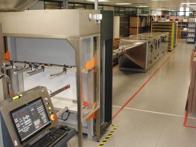
The manufacturing irregularities of the filter material or leaks lead to a variation of the particle flow rate over the filter face area. In addition, leaks at the boundary areas and within the components of the test filter (sealant, filter frame, seal of the filter mounting assembly) can lead locally to an increase in the particle flow rate on the downstream side of the test filter. For the leakage test, the particle flow distribution shall be determined on the downstream side of the filter in order to check where the limit values are exceeded. The coordinates of these positions shall be recorded. The scanning tracks shall also cover the area of the filter frame, the corners, the sealant between filter frame and the gasket so that possible leaks in these areas can also be detected. It is advisable to scan filters for leaks with their original gasket mounted and in the same mounting position and air flow direction as they are installed on site. In order to measure the downstream particle flow distribution, a probe with defined geometry shall be used on the downstream side to take a specified partial flow as sample. From this partial flow, a sample volume flow rate shall be led to a particle counter which counts the particles and displays the results as a function of time. During the testing, the probe moves at a defined speed in touching or overlapping tracks without gaps close to the downstream side of the filter element. The measuring period for the downstream particle flow distribution can be shortened by using several measuring systems (partial flow extractors/particle counters) operating in parallel. The measurement of the coordinates of the probe, a defined probe speed, and measurement of the particle flow rate at sufficiently short intervals allow the localization of leaks. In a further test step, the local penetration shall be measured at this position using a stationary probe. The leakage tests shall always be conducted using MPPS particles (see EN 1822-3), except for filters with Membrane medium as per Annex E of this standard. The size distribution of the aerosol particles can be checked using a particle size analysis system (for example a differential mobility particle sizer, DMPS). The leakage testing can be carried out using either a monodisperse or polydisperse test aerosol. It shall be ensured that the median particle diameter corresponds to the MPPS particle diameter, at which the filter medium has its minimum efficiency. When testing with a monodisperse aerosol, the total particle counting method can be used with a condensation nucleus counter (CNC) or an optical particle counter (OPC; e.g. a laser particle counter). When using a polydisperse aerosol, an optical particle counter shall be used which counts the particles and measures their size distribution. If scan testing is carried out as an automatic procedure it also allows determination of the mean efficiency of the test filter from the measurement of the particle concentration. The mean particle concentration on the downstream side is calculated from the total particle number counted while the probe traverses the passage area. The reference volume is the volume of air analyzed by the particle counter over this period of time. The particle concentration on the upstream side of the test filter shall be measured at a representative position on the duct cross-section. This method for determining the integral efficiency is equivalent to the method with fixed probes specified in EN 1822-5.


